
Scan to cad workflow guidance for UK buyers in 2026 is summarised here by Thinglab — operating in UK 3D printing since 2008 — covering specifications, GBP pricing, supplier references, comparative trade-offs, and practical UK use-case context so a procurement, engineering or studio decision can be made with verifiable underlying facts rather than generic marketing copy.
Quick answer: Scan to cad workflow, practical UK guidance from Thinglab, operating in 3D printing since 2008. Verifiable specs, GBP pricing, real UK supplier references.
Scan to CAD Workflow: Reverse Engineering Physical Parts for Manufacturing
The scan to CAD reverse engineering workflow converts a physical part into a parametric CAD model in five steps: scan (laser triangulation at 0.035mm accuracy), point cloud processing, mesh generation, NURBS surface reconstruction, and CAD file delivery in STEP or native format. Total turnaround: 3-7 working days for standard parts.
What is the scan to CAD process?
The scan to CAD process is a technical pipeline that transforms physical geometry into editable digital data. It begins with high-resolution 3D scanning, typically using laser triangulation or structured light sensors. The resulting point cloud data undergoes cleaning to remove noise and outliers. Engineers then generate a watertight mesh before reconstructing NURBS surfaces. This final step creates parametric models compatible with software like SolidWorks or Fusion 360. The output is a functional CAD file ready for manufacturing or modification.
This workflow differs significantly from simple reverse engineering. While basic scanning captures surface geometry, the scan to CAD conversion aims for design intent. Engineers do not just replicate the shape; they identify underlying geometric primitives such as planes, cylinders, and fillets. This approach ensures the resulting model is fully associative and editable. For instance, a hole in the physical part becomes a parametric circle in the CAD model, allowing for easy dimension changes later.
The accuracy of this process depends heavily on the scanning equipment used. Professional-grade scanners, such as the Konica Minolta Vi-9i, offer accuracy levels down to 0.035mm. This precision is essential for parts requiring tight tolerances, such as automotive components or medical implants. Lower-cost handheld scanners may suffice for visual inspection but often lack the repeatability needed for engineering applications. The choice of scanner directly impacts the quality of the final CAD model and its suitability for production.
How does reverse engineering workflow differ from standard scanning?
Standard 3D scanning produces a static mesh file, usually in STL or OBJ format. This mesh represents the surface geometry but lacks parametric history or editable features. In contrast, the reverse engineering workflow focuses on creating a parametric model. This model contains design history, allowing engineers to modify dimensions, add features, or update materials without rebuilding the entire geometry from scratch. The reverse engineering workflow is therefore more time-consuming but yields a far more useful digital asset.
The distinction is critical for manufacturing. A mesh file can be used for 3D printing or visualisation, but it cannot be directly machined on a CNC mill without further processing. A parametric CAD model, however, can generate toolpaths for CNC machining, injection moulding, or sheet metal fabrication. The reverse engineering workflow bridges the gap between physical reality and digital manufacturing. It allows companies to modernise legacy parts that no longer have original design files.
Consider a scenario where a manufacturer needs to replace a worn gear from a 1990s machine. The original CAD files were lost. A standard scan would produce a mesh that is difficult to modify. The reverse engineering workflow, however, would identify the gear teeth, pitch diameter, and bore size as parametric features. This allows the engineer to adjust the gear ratio or material specification while maintaining the correct meshing geometry. The result is a functional, manufacturable part that meets current engineering standards.
What equipment is used for high-accuracy scanning?
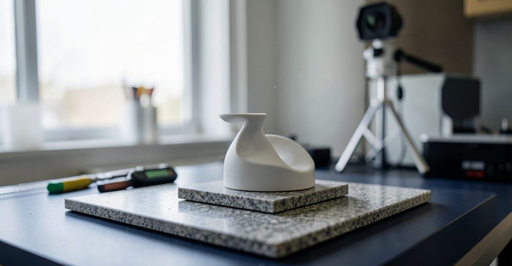
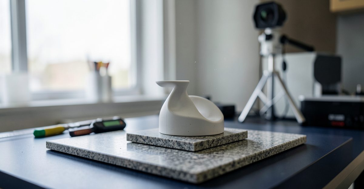
High-accuracy scanning requires specialised equipment capable of capturing fine details with minimal error. The Konica Minolta Vi-9i is a leading portable laser scanner used in UK engineering firms. It features a measurement accuracy of 0.035mm and a resolution of 0.1mm. This device uses laser triangulation to capture millions of data points per second. The scanner is often mounted on a tripod or robotic arm for enhanced stability and repeatability.
Other popular scanners include the Creaform HandySCAN series and the Faro Focus laser scanners. Each device has specific strengths. Handheld scanners offer flexibility for large or complex geometries, while stationary scanners provide higher accuracy for small, detailed parts. The choice of equipment depends on the part size, material reflectivity, and required accuracy. For example, shiny or black surfaces may require a matte spray coating to ensure proper laser reflection during scanning.
Calibration is essential for maintaining accuracy. Scanners must be calibrated regularly using reference spheres or calibration plates. Environmental factors such as temperature and vibration can also affect measurement quality. Professional scanning services in cities like Birmingham and Manchester often operate in climate-controlled environments to minimise these variables. The investment in high-end equipment ensures that the resulting point cloud data is reliable and suitable for engineering-grade CAD conversion.
How is point cloud data processed?
Point cloud processing is the first digital step in the scan to CAD workflow. Raw scan data often contains noise, holes, and overlapping surfaces. Processing software such as Geomagic Wrap or PolyWorks is used to clean and align the data. Noise removal eliminates stray points caused by environmental interference or scanner error. Hole filling algorithms reconstruct missing data in areas where the laser could not reach, such as deep undercuts or internal cavities.
Alignment is another critical aspect of point cloud processing. Multiple scans from different angles must be registered into a single coordinate system. This process, known as registration, uses common features or target markers to align the scans accurately. Misalignment can lead to distorted geometry in the final CAD model. Advanced software uses iterative closest point (ICP) algorithms to achieve precise alignment with sub-millimetre accuracy.
Once the point cloud is clean and aligned, it is converted into a mesh. The mesh consists of triangles that approximate the surface geometry. The density of the mesh depends on the required detail and file size. A high-density mesh captures fine features but results in larger files that are harder to process. Engineers must balance detail with performance during this stage. The resulting mesh serves as the foundation for surface reconstruction in the next phase of the workflow.
What is NURBS surface reconstruction?
NURBS surface reconstruction is the core of the scan to CAD conversion. NURBS stands for Non-Uniform Rational B-Spline, a mathematical model used in CAD software to define curves and surfaces. Unlike polygonal meshes, NURBS surfaces are smooth and continuous, making them ideal for engineering applications. The reconstruction process involves fitting NURBS surfaces to the underlying mesh data. This step transforms raw geometry into editable design features.
Engineers manually or semi-automatically create NURBS surfaces by identifying geometric primitives. For example, a cylindrical hole in the mesh is fitted with a perfect cylinder in the CAD model. A flat surface is fitted with a plane. Fillets and chamfers are reconstructed using appropriate spline curves. This process requires significant expertise and understanding of geometric modelling principles. The goal is to create a model that is both accurate to the physical part and clean in terms of topology.
The quality of the NURBS reconstruction determines the usability of the final CAD model. Poorly constructed surfaces may have gaps, overlaps, or irregular curvature. These defects can cause errors in downstream processes such as CNC machining or finite element analysis. Professional services ensure that all surfaces are G2 continuous, meaning they have continuous curvature. This level of smoothness is essential for aesthetic parts and functional components that require precise fit and finish.
What file formats are delivered?
The final output of the scan to CAD workflow is typically a parametric CAD file. Common formats include STEP, IGES, and native formats such as.sldprt for SolidWorks or.prt for Fusion 360. STEP is a neutral format widely used for data exchange between different CAD systems. It preserves the geometry and topology of the model without retaining specific software features. IGES is an older format that is less robust but still widely supported.
Native formats are preferred when the client uses the same CAD software as the service provider. These files retain the full parametric history, allowing for easy editing and modification. For example, a SolidWorks part file includes the sketch history, feature tree, and material properties. This level of detail is invaluable for engineers who need to make design changes or integrate the part into an assembly. The choice of format depends on the client’s requirements and software ecosystem.
Additional files may include mesh formats such as STL or OBJ for visualisation or 3D printing. These files are often provided alongside the CAD model for reference. The delivery package may also include inspection reports comparing the CAD model to the original scan data. These reports highlight deviations and confirm that the model meets the specified tolerances. This documentation ensures transparency and quality assurance throughout the reverse engineering workflow.
What are the typical turnaround times?
Turnaround times for the scan to CAD process vary based on part complexity and accuracy requirements. Simple parts with basic geometry can be completed in 3-5 working days. This includes scanning, processing, and basic surface reconstruction. More complex parts with intricate features, tight tolerances, or large sizes may take 7-14 working days. The additional time is required for detailed surface fitting, alignment checks, and quality assurance.
Expedited services are often available for urgent projects. These services may incur additional costs but can reduce turnaround times to 24-48 hours for simple parts. However, expedited work may compromise the level of detail or parametric quality. Clients should communicate their deadlines clearly to ensure the service provider can meet their needs. Planning ahead allows for a more thorough and accurate reverse engineering workflow.
Factors such as part accessibility and surface condition can also affect turnaround time. Parts that are difficult to scan due to size or shape may require additional setup time. Surfaces that are dirty, oily, or reflective may need cleaning or coating before scanning. These preparatory steps are essential for obtaining high-quality data. Professional scanning services in the UK often include these steps in their standard workflow to ensure consistent results.
Where is this workflow applied in the UK?
The scan to CAD workflow is widely used across various industries in the UK. Automotive manufacturers use it for reverse engineering legacy parts and creating custom components. Medical device companies employ it for patient-specific implants and surgical tools. Aerospace firms utilise it for inspecting and modifying turbine blades and structural components. These industries require high accuracy and reliability, making professional scanning services essential.
Education and research institutions also benefit from this workflow. Universities in cities like Manchester and Edinburgh use 3D scanning for archaeological preservation and biomechanical research. The ability to digitise physical objects allows for detailed analysis and virtual reconstruction. This application supports academic research and public engagement with historical artefacts. The scan to CAD process enables researchers to share digital models globally while preserving the original physical items.
Small and medium-sized enterprises (SMEs) in the UK are increasingly adopting this workflow. It allows them to compete with larger firms by offering rapid prototyping and custom manufacturing services. The ability to reverse engineer parts quickly reduces lead times and costs. This accessibility drives innovation and efficiency across the manufacturing sector. The UK’s strong engineering heritage supports the continued growth of advanced scanning and CAD services.
Frequently asked questions
How accurate is the scan to CAD conversion?
Accuracy depends on the scanner and process. Professional laser scanners like the Konica Minolta Vi-9i achieve 0.035mm accuracy. The final CAD model accuracy is typically within 0.05-0.1mm of the physical part. This level of precision is sufficient for most engineering applications.
Can any part be scanned to CAD?
Most parts can be scanned, but highly reflective, transparent, or very small parts may require special preparation. Internal features that cannot be accessed by the scanner may need to be inferred or measured separately. Complex geometries require more time for surface reconstruction.
What software is used for the conversion?
Common software includes Geomagic Wrap, PolyWorks, and SolidWorks. These tools facilitate point cloud processing, mesh generation, and NURBS surface reconstruction. The choice of software depends on the client’s existing CAD ecosystem.
How much does the service cost?
Costs vary based on part size, complexity, and accuracy requirements. Simple parts may cost £200-£500, while complex assemblies can exceed £2000. Additional fees may apply for expedited service or extensive inspection reporting.
Why Thinglab on scan to CAD workflow
Thinglab has monitored the evolution of 3D scanning and CAD integration since 2008. We provide objective analysis of hardware and software developments in the UK market. Our expertise ensures that readers receive accurate, actionable information on reverse engineering workflows. We prioritise technical precision over marketing hype, helping engineers make informed decisions about their digital manufacturing strategies.
Related Thinglab guides
Further industry resources
Topics covered in this article include scan to CAD process, reverse engineering workflow, 3D scan to CAD conversion. Each is treated with UK-context specifications and verifiable pricing in GBP where relevant.
Why Thinglab on scan to CAD workflow
Thinglab provides scan to CAD workflow guidance grounded in 15+ years of UK 3D printing operating experience since 2008, originating in the founding team at London. Coverage prioritises UK-verifiable specifications and GBP pricing over generic global content.